


 86-312-3156390


TZY-KC3000-S series intelligent control device
Add time:2022-02-21
Page views:218
 Dial +86-312-3156390 / 3155390
The TZY-KC3050-S intelligent control device for switchgear is a new type of multifunctional analog dynamic display and control device suitable for use with various high and low voltage switchgear. It has the characteristics of complete functionality, compact structure, vivid and intuitive display, sensitive and reliable response. It can replace many traditional components such as primary circuit simulation signs, electromagnetic switch status displays, grounding indicators and heating controllers installed on switchgear, reduce the number of components, and simplify the structure of switchgear. This series of products has stable performance, easy installation, long service life, and excellent environmental tolerance and electromagnetic compatibility, and can operate reliably for a long time.
The TZY-KC3050-S intelligent control device for switchgear integrates multiple functions such as displaying circuit breaker status, switch status, grounding knife status, spring energy storage status, high-voltage live indication, high-voltage live locking control, and environmental temperature and humidity control through a primary circuit simulation diagram. Each function can be freely combined. In addition, this series of products adopts microcontroller technology to collect the working status of various components in the switchgear, control heating, and diagnose heating circuit faults; It can simultaneously measure and control two temperature and humidity signals in real-time, and display temperature and humidity data in digital form; Simultaneously using software approval technology to compensate for temperature and humidity drift counting errors and component nominal errors, the measurement and control accuracy is high, and installation, use, and maintenance are simple and convenient.
The intelligent control device of TZY-KC3050-S switchgear can communicate with the background monitoring computer network through RS-485 bus, facilitating real-time dynamic operation simulation and remote environmental monitoring of electrical primary systems composed of multiple switchgear. The intelligent control device of TZY-KC3050-S switchgear has excellent environmental tolerance and electromagnetic compatibility performance. Anti interference technology, optoelectronic and electromagnetic isolation, selection of high-quality components, three proof treatment of circuit components, and strict measures such as live aging and factory testing ensure the long-term reliability of the product.
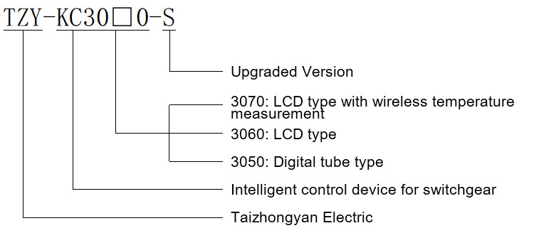
Model description:
1. Working power supply: AC or DC 110V~265V
2. Usage environment: Temperature -20 ℃~70 ℃ Relative humidity<95% rh="">
3. Whole machine power consumption:<5w<>
4. Electrical strength: AC2000V 50Hz for 1 minute
5. Insulation performance: tested with a 500V megohmmeter, not less than 100M Ω
6. Description of switch status display
6.1 Circuit breaker status indication (passive contact input)
The green analog bar lights up when the circuit breaker is opened
When the circuit breaker is closed, the red analog bar lights up
6.2. Hand cart position indication (passive contact input)
When the test position contacts are closed, the green simulation bar lights up
When the working position contacts are closed, the red analog bar lights up
6.3. Grounding knife status indication (passive contact input)
When the grounding knife is disconnected, the green analog strip lights up
When the grounding knife is closed, the red simulated strip lights up
6.4. Spring energy storage status indication (passive contact input)
When the circuit breaker operating mechanism is not storing energy, the spring symbol appears green
When the operating mechanism of the circuit breaker has stored energy, the spring symbol appears in red
Note: All status display input signals are taken from the auxiliary contacts of the primary components in the switchgear (passive contact type).
6.5. Voice anti error prompt (optional function)
1) When the circuit breaker is in the closed state and the handcart is mistakenly pushed from the test position to the working position, or when the handcart is mistakenly pushed from the working position to the test position, a voice prompt will appear saying "Please disconnect the circuit breaker";
2) When the grounding switch is in the closed state and the handcart is mistakenly pushed from the test position to the working position, a voice prompt will appear saying "Please disconnect the grounding switch";
3) When the circuit breaker is in the closed state and the grounding switch is in the closed state, and the handcart is mistakenly pushed from the test position to the working position, a voice prompt will appear saying "Please disconnect the circuit breaker, please disconnect the grounding switch";
4) When the handcart is in the working position and the grounding switch is accidentally operated, the voice prompt "Please disconnect the grounding switch" appears when it is closed;
7. High voltage live indication
Indicate that the starting voltage is greater than 0.08 bus voltage
Locking start control voltage>0.08 bus voltage
Lock output contact normally closed passive contact rated capacity AC220V/3A
Warning: Merely relying on a live indicator is not enough to prove that the system is no longer live; If the program requires it as a mandatory requirement, relevant voltage detectors or voltage detection devices that comply with IEC61243 should also be used.
8. Temperature and humidity control
8.1 Two channel temperature and two channel humidity
When the ambient temperature is below the lower temperature limit, the device automatically starts the heater to heat up, and the ambient temperature begins to rise. When it reaches the temperature at which heating stops (i.e. the lower temperature limit+temperature return value), the device automatically stops heating.
When the ambient humidity is higher than the set value, the device automatically starts the heater to heat up, and the ambient humidity begins to decrease. When the humidity drops to the point where heating stops (i.e. the humidity set value humidity return value), the device automatically stops heating.
8.2.1 Measurement and Control Range
Temperature: -40 ℃ to+80 ℃
Humidity: 0% RH to 99.9% RH
8.2.2 Resolution
Temperature: ± 0.1 ℃
Humidity: ± 0.1% RH
8.2.3 Measurement and Control Accuracy
Temperature: ± 0.5 ℃
Humidity: ± 3% RH
8.3 Parameter Setting Range and Description
8.3.1. Temperature lower limit setting range: 0-25 ℃, the lower temperature limit is used to start heating.
8.3.2. Temperature hysteresis range: 1-10 ℃, temperature hysteresis+temperature lower limit=stop heating.
8.3.3 Humidity: 60-90% RH (heating), start heating when the ambient humidity is higher than the set value.
8.3.4. Humidity hysteresis range: 1-30% RH, humidity constant - humidity hysteresis is the humidity value at which heating stops.
8.4 Heating control output contact: normally open passive contact, rated capacity AC220V/3A.
8.5. Heating circuit disconnection alarm output contact: normally open passive contact, rated capacity AC220V/3A.
9. Communication
Interface type RS-485.
The communication speed can be selected from 1200/2400/4800/9600bps.
Communication protocol MODBUS protocol RTU mode.
10. Opening and closing function
The device is equipped with opening/closing switch, remote/local switch, energy storage switch, and lighting switch, which can respectively perform corresponding functions.

Simulated Display Diagram
Ordering Instructions
1. Please inform us of the product model, name, and order quantity.
2. Please provide a simulated wiring diagram for the main circuit.
3. Please indicate the load of the heater circuit.
4. Please indicate the length of the sensor cable.
5. Please advise whether the high-voltage live display sensor only comes with this device. If it also comes with high-voltage live display devices from other manufacturers, please inform us in advance.
6. If there are any special functions, please provide detailed explanations before placing an order.


 冀公网安备 13065202000415号
 Home
Home Tel
Tel Product